Voltage Divider Arduino Circuit Diagram
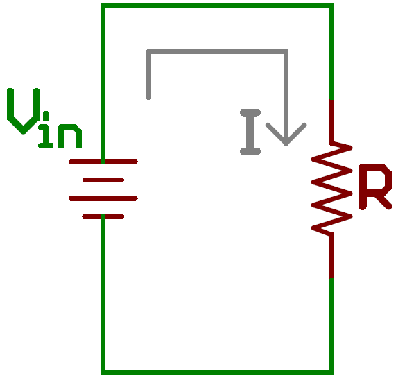
Voltage Divider Arduino Circuit Diagram Learn how to calculate the voltage drop, resistance, current, and output voltage in a voltage divider circuit. A voltage divider is a simple circuit that can reduce voltage by distributing it among the components of the circuit.
Learn how to use a voltage divider circuit to create a smaller voltage from an input voltage with two resistors. Find the output voltage formula, a calculator, and examples of voltage divider applications.

Basic Electronics Tutorials and Revision Circuit Diagram
Learn about voltage divider, a passive linear circuit that produces an output voltage that is a fraction of its input voltage. Find out how resistors, capacitors and inductors affect the voltage division and the frequency response of the circuit. Learn how to use voltage dividers to convert an input voltage into an output voltage that is a fraction of it. Explore resistive, capacitive and inductive voltage divider circuits with examples and applications.

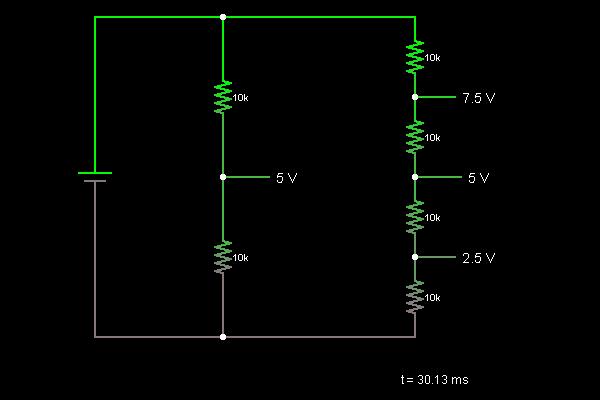
It is actually the divider voltage that we get from this circuit as the output. Equation of Voltage Divider in Unloaded Condition. The simple voltage divider circuit with reference to the ground is shown below. It has two electrical impedances (Z 1 and Z 2) or any passive components connected in series.These impedances can be resistors, inductors, or capacitors.

Voltage Divider: What is it? (Circuit And Applications) Circuit Diagram
Learn how to calculate voltage drops in series circuits using the voltage divider formula and the voltage divider ratio. Explore the applications and examples of voltage dividers and potentiometers in electric circuits.
Learn what a voltage divider circuit is, how it works, and how to calculate its output voltage. Explore the different types of voltage dividers (resistive, capacitive, and inductive) and their applications in electronics and measurement devices.